The history of drawing is elapsed where mankind existence. That sketching or drawing were the people early medium of communicating bring the things forward with over time for future.
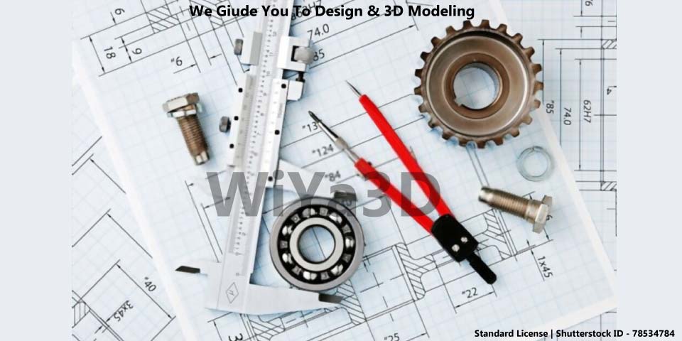
Engineering drawing is a common communication tool to representation of product, part or construction. That are develop or manufacture for human use. Guideline for the engineering drawing were standardized in order to use and understand representation of every drawing in internationally/globally. Even today drawings are develop by manually or by computerized digital methods.
Purpose of Engineering Drawings
Engineering drawings also have specific purpose in representing dimensions, component names, assembly component details, manufacturing/machining requirement, fit & tolerances, surface finish details and other information may be included. Because of this, an engineer may begin production as soon as he receives the design
Making Drawings
Manual Drafting/Drawing
When talking about manual or traditional drawing engineer/designer draw the every detail of drawing manually with specific set of tools & accessories.
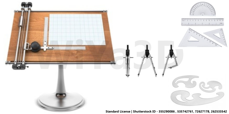
- Pencils
- Drawing Sheet
- Drawing Board
- T -Square
- Set Squares
- Protractor
- Mini Drafter
- Compass / Divider
- French Curves
- Roll & Draw
- Drafting Template Set
- Sheet Holding Clips
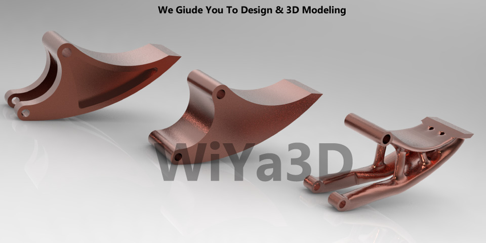
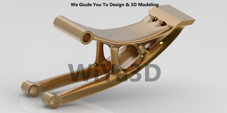
However Now a days CAD software are used for drawing, that one can create drawings from scratch with CAD in short time of period. To produce drawings, it is better to build a 3D model first and then use that model as a starting point. It’s as simple as adding up the measurements. Having models also simplifies the process of revising the drawings in the event of changes.
Main Components of an Engineering Drawing
Layout & Size of Drawing Sheet
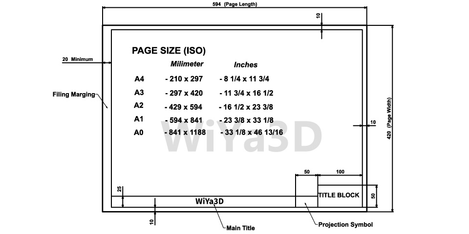
Above shown the general/standard drawing layout that can be used for technical drawing. Although based on the company requirement or specific standard followed it may be little customize the layout. These layout boarder margin kept for filing purposes.
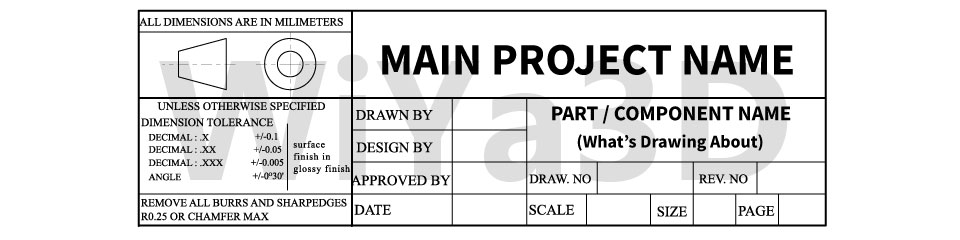
Title block revels the information of the drawing such as drawing title, part detail, scale, author, date, sheet number, identification reference,…etc
The drawing sheets are A0 – A4 (or to A5) trimmed sizes being used. After the drawing are made all the sheet are folded to A4 size.
Types of Lines
Drawing lines are representing internal/external surface of a object as straight or curved in continuous or segmented manner.
Continuous Line
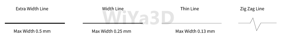
Extra Width Lines – used to represent visible outline or special lines
Normal Width Lines – used to represent ground lines, visible outlines of parts, reference lines, visible outline of cut-section, boarder lines, title block,…etc
Thin Lines – used to represent construction lines, projection lines, extension lines, dimension lines, hatching lines, Leader lines,…etc
Zig Zag Lines – represent long break line or interrupted views
Dashed Lines / Hidden Lines

Dashed lines are used to represent the hidden lines/edges & hidden outlines.
Long Dashed Dotted Lines

This type of lines are used to represent center lines, symmetry lines, pitch circle of holes, cutting planes & surface treatment indication locations
Views

Each view ( Front, Top, Side, Bottom, Isometric,…) has a distinct function to fulfill. Based on the model part and which detail going to include or represent in the drawing designer need to select the relevant views in the drawing. It’s good practice to provide distributed dimension mark on the part drawing along the number of views represent in the drawing. If the single view doesn’t provide or not necessary showing in the drawing, most of the time it can omit adding that view to the drawing
Orthographic Projection
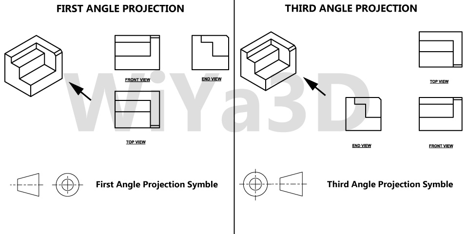
An engineering drawing’s orthographic view is one of the most popular perspectives. As a result of orthographic projection, a 3D object may be represented in 2D. This guarantees that everything required for component manufacturing is transported. In addition, there is no length distortion of any type.
Cutout / Sectional View
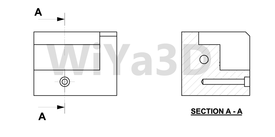
Cutouts or section view mostly used to provide the inside detail of part/assembly, that cannot be represent or clearly show with hidden lines in perspective views. In the basis of the engineering drawing it’s not good practice to provide dimension on hidden lines. Therefore section views are used to provide detail and measurement inside the part/assembly.
Detail View
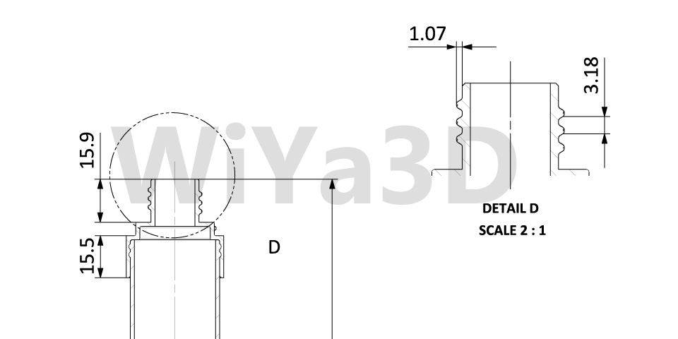
Details view are used to provide more depth & finer details of specific section or area of a larger view. This is helpful if the tiny area contains significant dimensions and provides a clear view of the measurements & shape. Representing of thread parameter, gear teeth details are mostly shown in this detail view.
Auxiliary View
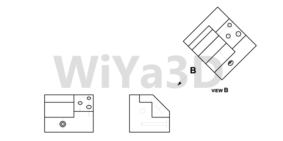
This is another orthographic projection view, that used to represent inclined or non-vertical/horizontal object & surface details.
Multi-View Projections
Multi-view projection is a method that may be used to accurately depict the shape and scale of an object by projecting two or more images at an angle of 90 deg. to one another or at predetermined angles.
Generally, this projection technique is used to accomplish engineering tasks. The finished design is then printed and sent to the shop or work location. Descriptions must be developed to design and convey to manufacturing groups every element (engineers, technicians). This description must be exact in its description of the shape and size of each component and the whole structure. As a result of this need, graphics are the main method of communication, with the term language used only to refer to notes and specifications. The projection theory framework offers the necessary underlying knowledge for shaping representations in graphics.
Engineering Drawing Practices
Layout Drawing
A layout drawing outlines the requirements for design development. It is similar to a detail, assembly or installation drawing but the visual, graphical, or dimensional data is presented in the amount needed to convey the design solution used in the creation of other design drawings. Applications. For a full finished product or portion thereof, a drawing may be generated and created, either as
- A conceptual design layout, which will offer one or more solution to satisfy the fundamental design requirements and form the basis for analyzing and selecting an optimal design approach.
- Layout of design approval to provide enough details for the cost estimation and design approval method.
- A comprehensive design layout showing the final project design to enable detail development and assembly drawings in sufficient detail.
- Geometrical analysis for mechanical links, clearances or arranging movement.
Detail Drawing
Detail drawing gives the full definition of the final result of the component or pieces shown on the drawing. For each component shown in it, a comprehensive graphic set forth the item identification.
Drawing Mono-detail
Prepared to provide as much clarity as possible. Identifies all the part’s features: settings, dimensions, tolerances, compulsory processes, materials surface texture, coatings, safety finishes and markings.
Drawing Multi-detail
Details of two or more individually identifiable pieces in different perspectives or in distinct view sets in the same drawing
Assembly Drawing
The design and content of the assembly or assemblies shown therein are defined by the assembly drawing. It identifies items for each assembly. When a montage design includes specific criteria for one or more components utilised in a montage, it is a detailed montage drawing.
Application. For each set of objects to be attached to create a montage and to reflect one or more of the following, an assembly design is produced
- A logical level in the assembly or disassembly process.
- An object that can be tested.
- A feature item.
- An object that can be delivered.
Conclusion
Engineering drawing continues to be a significant part of the work of a machinist. These drawings may account for up to 20% of the time spent on design work. This helps in the accurate representation of all the geometric characteristics of product and their components. In this manner, you can be certain that manufacturers will create components that suit your particular requirements.
In industrial applications, it is hoped that automating the interpretation of 3D models would decrease production time. Tolerance and assembly designs must be produced by the engineers independently. This strategy is helpful for creating better products.