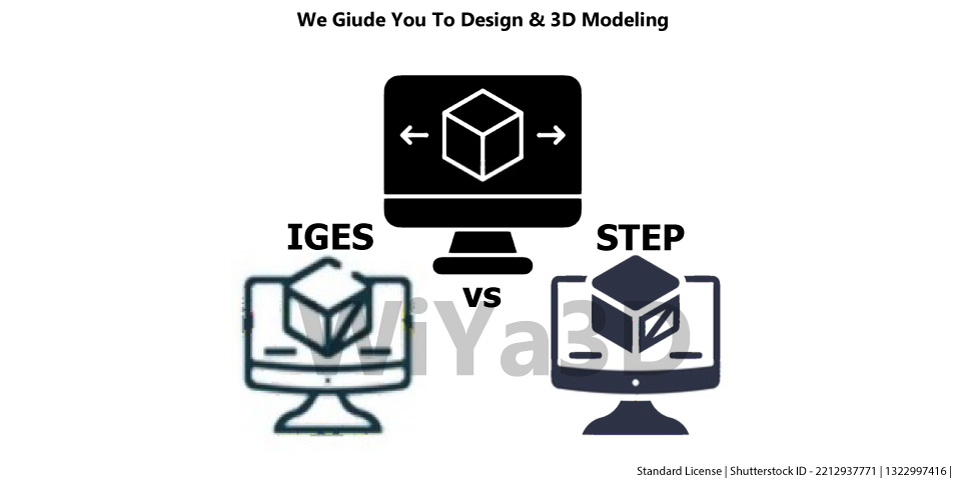
When it comes to exchanging 3D design data, two commonly used file formats are IGES and STEP. Both formats are widely accepted in the engineering and manufacturing industries, and each has its own set of advantages and disadvantages.
IGES File Format
IGES, or Initial Graphics Exchange Specification, is a file format that was developed in the 1980s as a way to transfer 3D design data between different computer-aided design (CAD) systems. It is a neutral file format, meaning that it is not tied to any specific software or system. This makes it a popular choice for exchanging data between companies or organizations that may use different CAD systems.
An IGES file includes a variety of CAD data such as,
- 2D/3D geometry (curves, surfaces,…)
- Drafting lines and Annotations
- Electronic/Piping schematic elements
- Finite element modeling elements
- Language/Product definition data
IGES Limitations
Import as Surface Model
IGES files are more commonly used for surface modeling, which may result in gaps and missing faces in the model when import/or open from another CAD package. Since it’s require to heal/modify and combined together the surfaces to get individual solid model.
Loss of Geometry Data During Exchange
During the import of an IGES model, the model is often converted to a surface model. However, surfaces are not intelligent and do not have information about their neighboring surfaces, which can result in gaps and missing faces during the translation process. This can be particularly problematic for complex models, which may have dozens, hundreds, or even thousands of separate surfaces and missing surface data. Repairs and post-processing of these models can be time-consuming and require additional effort.
Large File Size & Processing Time
IGES was notorious for its large file sizes and long processing times, which were a common source of frustration for users due to the limitations of computing power at the time. It was not uncommon for IGES files to take hours or even days to parse using the average computer of the time period.
Inaccuracies In The Geometry
When an IGES file is shared and imported into another CAD software, it is typically translated and converted again. This process of translation and conversion can introduce inaccuracies in the geometry, especially when compared to the STEP file format. This is because the IGES file is often translated into a surface model, which can result in gaps and missing faces in the model. In contrast, the STEP file format is more accurate and precise, as it is not limited to representing the model as a series of surfaces.
Not Support the Transfer of Design Intent,
meaning that any geometric tolerances or other design specifications are not preserved when the data is transferred.
STEP File Format
STEP, or Standard for the Exchange of Product Model Data, is a more modern file format that was developed in the 1990s. Like IGES, it is a neutral file format and is widely accepted in the engineering and manufacturing industries.
One major advantage of STEP over IGES is that it is able to preserve design intent, meaning that geometric tolerances and other design specifications are retained when the data is transferred. This is important for maintaining the accuracy and integrity of the design. Additionally, STEP files are generally smaller in size than IGES files, making them easier to work with and transmit.
STEP files contain product definition information that are similar to that found in IGES files, but also include additional information such as:
- Surface Colors & Material Properties
- Model Topology
- Tolerances
In terms of which file format is better, it really depends on your specific needs and requirements. If you are simply looking to exchange basic 3D design data between different CAD systems, then IGES may be sufficient. However, if you need to preserve design intent and accuracy without loss of gematric data, or if you need to work with larger and more complex designs, then STEP may be the better choice.


