Reverse engineering is the process of analyzing an existing product or system in order to understand its design and function, and then creating a new product or system based on that understanding. This process often involves using computer-aided design (CAD) software to create 3D models of the existing product or system.
Reverse Engineering Design Process
The reverse design is a method used in deconstruction of an object to figure out how it is made. It involves determining the principle and technological functionality of a device, object or system through analysis using computer software, electronic or mechanical devices. To reverse design in CAD, you need to use a CAD enabled computer software to digitize complex shapes or physical parts to convert them into computer-aided design models. Below is the step by step process to reconstruct objects.
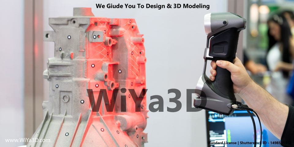
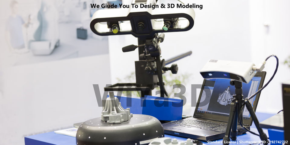
3D Scanning
Using 3D scanning techniques, the original/existing object is 3d scanned and captured the three-dimensional point clouds data in computer digital format. The captured 3D scanned data consist of XYZ object pont data, texture, shape & size for further processing and reverse design. 3D scanning techniques, to collect complex information such as dimensions that would be difficult to do by hand & conventional measuring equipment like vernier caliper, micrometer screw Meter,… These digital data is used to analyze the construction of a new 3d computer digital file for the subject.
Processing 3D Scan Data
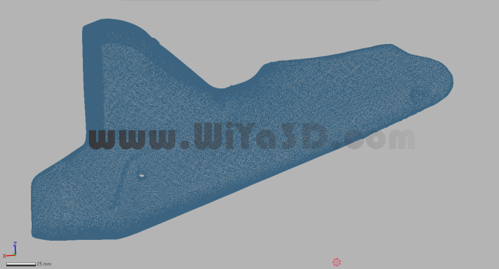
The digital data that is captured from 3D scanner generally captured and converted to a mesh or a point cloud. At this point, Reverse Engineering CAD software comes, and it’s is used to analyze and deconstruct the data to create a new 3D scanned model file by aligning ( align the few number of scanned data which taken from differently), reduce noises, filling holes (which are not captured during 3D scanner), reconstruct the mesh with optimize point density, and smoothed mesh/clean up the point cloud data. All these mesh or point clouds editing done within the tolerance, that desired for the product in order to maintain the accuracy and shape.
Surface Creation & CAD Modeling
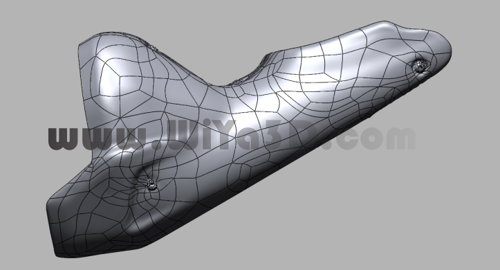
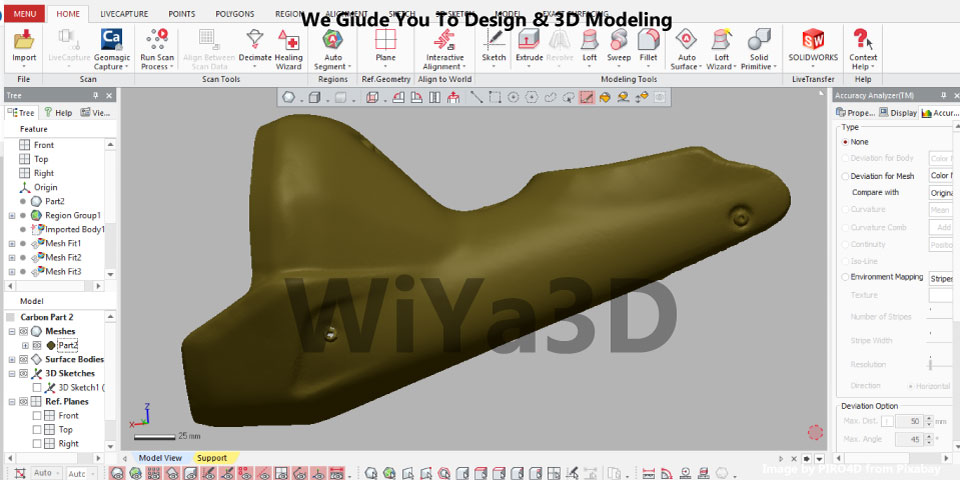
At this stage, the scanned data serves as a reference to build the CAD file. 3D digital models are generated through the 3D model generation process in the CAD system. You can also add new features that might be relevant to the created model. Creative 3D rebuilding helps to generate an accurate prototype of the original design. A different Reverse Engineering CAD packages aid in constructing the surface/solid model from based 3D scan data to complete the same CAD file for the object yet editable in any available/leading CAD software.
Deviation Check & Verification 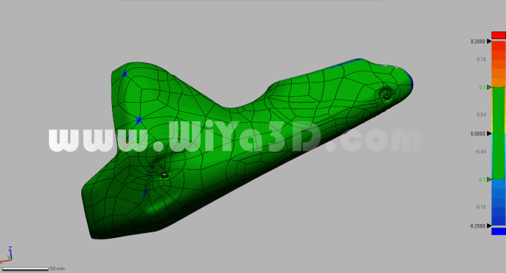
The CAD system enables simulation and evaluation of the reverse design model deviation with 3D scan data. If the reverse CAD model is not within the desired tolerance limit, then engineer/designer will be able to re modify and correct the deviation.
3D Printing & 3D Scan for Measurement Fit Check
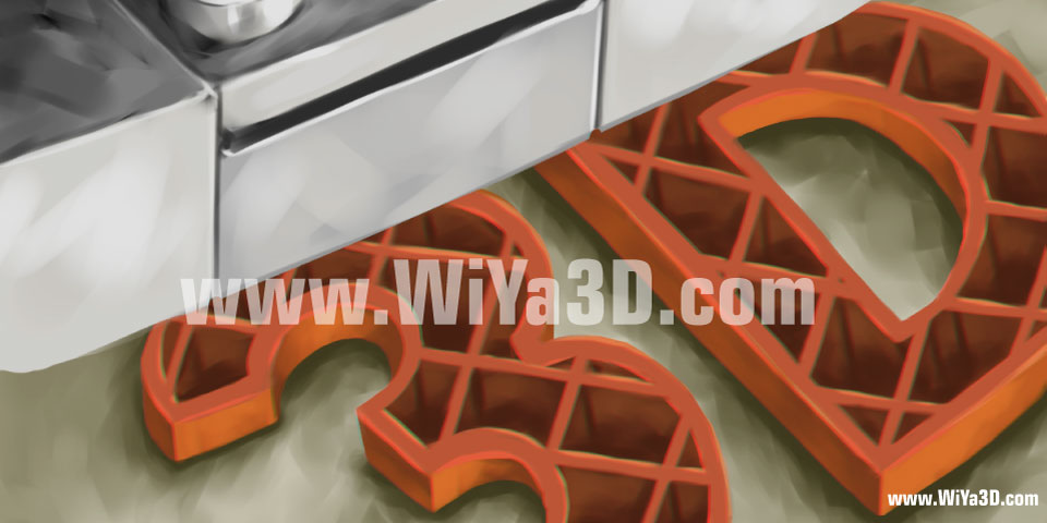
And further measure the dimension with CMM machine
In the final stage, an optimized new design is prototype. The prototype can be used to re-3D scan for measurement and actual fitment within the assembly review, before mass production the reverse engineered part.
The reverse engineering design is about using this technology for the future rather than bringing old parts to life Manufacturers use CAD reverse design to document existing objects, plan, evaluate and rebuild products to enhance functionality at the lowest possible cost.


