The first thing you need in a limits, tolerance & fit selection guide in part design is a clear understanding of the concepts of tolerance and fit.
What is Tolerance in Engineering Design
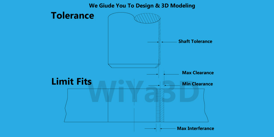
Tolerance is the range within, which the dimension is allowed to vary for part/assembly. Current manufacturing technologies are highly accurate, there are many factors that can affect the final dimensions of the final part. Therefore, engineering design considers these possible factors to allow the dimensional variation, but only when it falls within a defined range of values.
Lets take part/machine assembly, when the either of the assembled part wear or broken. Then new part need to replace. Therefore this new part had to made from measurements of the remaining parts of the assembly. In such a case making new part to replace is problematic that need to trial and error method and different has different precision level. There come the manufacturing interchangeable part with use of correct tolerance.
Generally tolerance should choose as large as possible, in order to reduce production challenges & cost of production. While meeting the optimal technical & functional requirement.
Tolerance Location
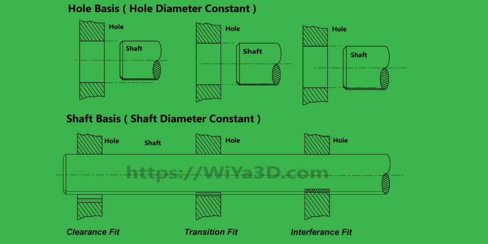
Tolerance location is denoted in relation to Holes basis or Shaft basis. In assembly hole or hole base geometry (cavity) and shaft or shaft/punch base geometry (Core) fit together. First hole base geometry (Cavity) side bored/machined to require diameter/or dimension and then shaft base geometry (Core) turned or machined to fit.
In production most preferred option is selecting hole base tolerance, that keeping hole dimension fixed to produce shaft. Because it’s always easy to turn/machine shaft to fit given hole than producing hole of specific diameter.
What is Fit in Engineering Design
Fit is a concept related to the assembly of two parts. A common example is the assembly of a shaft and a hole. Depending on how tight or how loose the parts need to be, a specific fit will be required.
Therefore, fit refers to the allowance between the two parts being assembled. In the case of a shaft and hole assembly, the fit makes reference to the maximum difference between the two diameters that is permitted for the assembly to work as expected per design.
The types of hole and shaft fits are:
- Clearance fit
- Transition fit
- Interference fit

How to select the right Fit & Tolerance
To select the right tolerance for the part being the designed, the designer must follow a series of steps.
- The first step is using the general tolerance chart provided by the organization, where the designer can find different types of materials, range sizes and general open tolerances. When the chart is not available, it is possible to reference existing drawings to obtain information.
- Perform a tolerance stack up analysis to make sure all the requirements are met.
- Perform Design For Manufacturing (DFM) hand in hand with manufacturers and suppliers. This must be done while understanding the capabilities of the available manufacturing processes.
- Verify the resulting information with the stack up analysis.
- Identify critical tolerances in drawings and make any required modifications.
How to select the right fit?
There are two systems that are commonly used to select the right fit for an assembly. The hole basis system and the shaft basis system.
From the names, it is easy to understand that the hole basis system uses the base dimension of the hole and adjusts the dimension of the shaft to achieve the required fit, and the shaft basis systems does the contrary by keeping the shaft to the base dimension.
Whatever the system used the right fit is selected according to the requirements of the assembly. Here is how:
- Clearance fit: this is when there is a positive allowance between the two parts. This is usually selected when lubrication, sliding or independent rotation is needed. In this case, the tolerances are determined so they never overlap.
- Transition fit: this is called transition because it is the midpoint between clearance and interference fit. When the tolerances are defined, both clearance and interference scenarios are possible. This is useful when high precision is required and movement needs to be permitted but controlled.
- Interference fit: this type of fit always results in dimensions overlap no matter the tolerance combination. This is a common fit for assemblies where the movement between two parts needs to be restricted.


