• About Us
  • Privacy & Policy
  • Forum Rules
  • Contact Us
Thursday, May 15, 2025
  • Login
  • Register
  • Home
  • Product Design
  • Categories
    • Latest CAD Technology
    • Engineering CAD Design
    • Design & 3D Modeling
    • 3D Modeling & 3D Creation
    • Design Tips & Guide
    • Product Design
    • 3D Rendering
    • 3D Animation
    • Architectural Design
    • Rapid Prototyping
    • 3D Printing
    • FEA & Engineering Simulation
    • Reverse Engineering Design
    • 3D Scanning
    • CNC & CAM Programing
    • Manufacturing Design
    • Manufacturing
    • Material Selection
  • CAD Forum
    • Forum – Engineering Design
    • Forum – 3D Modeling & 3D Creation
    • Forum – 3D Scan & Reverse Engineering Design
    • Forum – FEA & Engineering Simulation
    • Forum – Architectural Design
    • Forum – Prototyping & 3D Printing
    • Forum – CNC / CAM Programming
    • Forum Rule
  • Privacy Policy
  • Contact Us
No Result
View All Result
CAD Forum
  • Home
  • Product Design
  • Categories
    • Latest CAD Technology
    • Engineering CAD Design
    • Design & 3D Modeling
    • 3D Modeling & 3D Creation
    • Design Tips & Guide
    • Product Design
    • 3D Rendering
    • 3D Animation
    • Architectural Design
    • Rapid Prototyping
    • 3D Printing
    • FEA & Engineering Simulation
    • Reverse Engineering Design
    • 3D Scanning
    • CNC & CAM Programing
    • Manufacturing Design
    • Manufacturing
    • Material Selection
  • CAD Forum
    • Forum – Engineering Design
    • Forum – 3D Modeling & 3D Creation
    • Forum – 3D Scan & Reverse Engineering Design
    • Forum – FEA & Engineering Simulation
    • Forum – Architectural Design
    • Forum – Prototyping & 3D Printing
    • Forum – CNC / CAM Programming
    • Forum Rule
  • Privacy Policy
  • Contact Us
No Result
View All Result
We Are 3D
No Result
View All Result

Limits, Fits and Tolerances Selection Guide in Design

in Design Tips & Guide, Engineering CAD Design, Manufacturing Design
Reading Time: 4 mins read
A A
Limits, Fits and Tolerances Selection Guide in Design
Limits Fits and Tolerance

The first thing you need in a limits, tolerance & fit selection guide in part design is a clear understanding of the concepts of tolerance and fit.

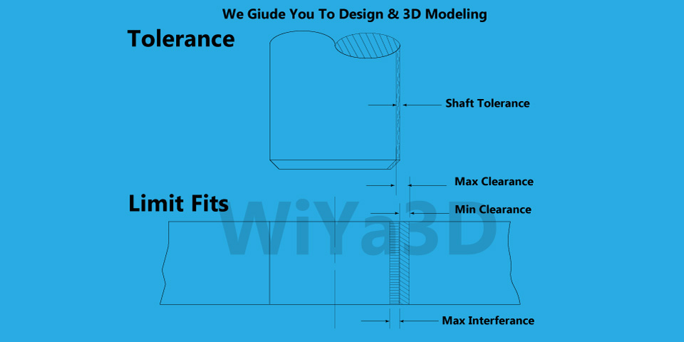
What is Tolerance in Engineering Design

Tolerance is the range within, which the dimension is allowed to vary for part/assembly. Current manufacturing technologies are highly accurate, there are many factors that can affect the final dimensions of the final part. Therefore, engineering design considers these possible factors to allow the dimensional variation, but only when it falls within a defined range of values.

Lets take part/machine assembly, when the either of the assembled part wear or broken. Then new part need to replace. Therefore this new part had to made from measurements of the remaining parts of the assembly. In such a case making new part to replace is problematic that need to trial and error method and different has different precision level. There come the manufacturing interchangeable part with use of correct tolerance.

Generally tolerance should choose as large as possible, in order to reduce production challenges & cost of production. While meeting the optimal technical & functional requirement.

Tolerance Location

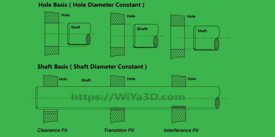
Tolerance location is denoted in relation to Holes basis or Shaft basis. In assembly hole or hole base geometry (cavity) and shaft or shaft/punch base geometry (Core) fit together. First hole base geometry (Cavity) side bored/machined to require diameter/or dimension and then shaft base geometry (Core) turned or machined to fit.

In production most preferred option is selecting hole base tolerance, that keeping hole dimension fixed to produce shaft. Because it’s always easy to turn/machine shaft to fit given hole than producing hole of specific diameter.

What is Fit in Engineering Design

Fit is a concept related to the assembly of two parts. A common example is the assembly of a shaft and a hole. Depending on how tight or how loose the parts need to be, a specific fit will be required.

Therefore, fit refers to the allowance between the two parts being assembled. In the case of a shaft and hole assembly, the fit makes reference to the maximum difference between the two diameters that is permitted for the assembly to work as expected per design.

The types of hole and shaft fits are:

  • Clearance fit
  • Transition fit
  • Interference fit
Limits Fits

How to select the right Fit & Tolerance

To select the right tolerance for the part being the designed, the designer must follow a series of steps.

  1. The first step is using the general tolerance chart provided by the organization, where the designer can find different types of materials, range sizes and general open tolerances. When the chart is not available, it is possible to reference existing drawings to obtain information.
  2. Perform a tolerance stack up analysis to make sure all the requirements are met.
  3. Perform Design For Manufacturing (DFM) hand in hand with manufacturers and suppliers. This must be done while understanding the capabilities of the available manufacturing processes.
  4. Verify the resulting information with the stack up analysis.
  5. Identify critical tolerances in drawings and make any required modifications.

How to select the right fit?

There are two systems that are commonly used to select the right fit for an assembly. The hole basis system and the shaft basis system.

From the names, it is easy to understand that the hole basis system uses the base dimension of the hole and adjusts the dimension of the shaft to achieve the required fit, and the shaft basis systems does the contrary by keeping the shaft to the base dimension.

Whatever the system used the right fit is selected according to the requirements of the assembly. Here is how:

  • Clearance fit: this is when there is a positive allowance between the two parts. This is usually selected when lubrication, sliding or independent rotation is needed. In this case, the tolerances are determined so they never overlap.
  • Transition fit: this is called transition because it is the midpoint between clearance and interference fit. When the tolerances are defined, both clearance and interference scenarios are possible. This is useful when high precision is required and movement needs to be permitted but controlled.
  • Interference fit: this type of fit always results in dimensions overlap no matter the tolerance combination. This is a common fit for assemblies where the movement between two parts needs to be restricted.
Tags: Fits and TolerancesLimits & Fits

Related Posts

Image Rendering Guide/Tips
3D Rendering

Image Rendering Guide/Tips

January 7, 2024
Engineering Drawing and Best Practice
Design Tips & Guide

Engineering Drawing and Best Practice

January 7, 2024
Load More
Please login to join discussion

Latest Post

Convert STL to Solid Body

December 31, 2024

Alternative for Geomagic Design X

December 31, 2024
Best Monitor Setup for CAD Engineers and 3D Modelers: Size, Panel Types, and Key Features

Best Monitor Setup for CAD Engineers and 3D Modelers: Size, Panel Types, and Key Features

September 5, 2024
Best Processor for CAD Modeling: A Guide to Intel, AMD Ryzen and Apple CPUs

Best Processor for CAD Modeling: A Guide to Intel, AMD Ryzen and Apple CPUs

September 3, 2024
3D Mesh Modeling vs. Engineering CAD Modeling: Key Differences and Best Software

3D Mesh Modeling vs. Engineering CAD Modeling: Key Differences and Best Software

September 1, 2024

About Us

We bring you the best CAD related information and knowledge. As a engineering team, which mainly in the field of Mechanical, Manufacturing, Product Development, Industrial,& Architectural. Our aim is share our experience on design & 3D modeling fields and give chance to everyone to get benefit of it.
Read More

  • Home
  • About Us
  • Contact Us

Copyright © 2019 - 2024 WiYa3D.com All rights reserved. Unauthorized reproduction or linking forbidden without expressed written permission. Registration on or use of this site constitutes acceptance of our Privacy Policy / Forum Rule & Posting Policies

Welcome to WiYa3D...!

Login to your account below

Forgotten Password? Sign Up

Create New Account!

Fill the forms bellow to register

*By registering into our website, you agree to the Terms & Conditions and Privacy Policy.
All fields are required. Log In

Retrieve your password

Please enter your username or email address to reset your password.

Log In
No Result
View All Result
  • Home
  • About Us
  • Categories
  • Privacy Policy
  • CAD Forum
    • Forum – Engineering Design
    • Forum – 3D Modeling & 3D Creation
    • Forum – 3D Scan & Reverse Engineering Design
    • Forum – FEA & Engineering Simulation
    • Forum – Architectural Design
    • Forum – Prototyping & 3D Printing
    • Forum – CNC / CAM Programming
  • Contact Us
  • Login
  • Sign Up
This website uses cookies. By continuing to use this website you are giving consent to cookies being used. Visit our Privacy and Cookie Policy.