Machining is a process of removing material from a workpiece/stock using a variety of tools and techniques. The goal of machining is to create a finished part with precise dimensions and a smooth surface finish. There are many different types of machining processes, including turning, milling, drilling, grinding, and more.
To successfully perform machining, two factors are essential: the tool must be harder than the material of the workpiece, and there must be relative motion between the tool and the workpiece. The process of chip formation begins with the application of pressure from the harder tool to the work material. The relative motion between the tool and the workpiece then causes the material to be sheared off, leading to the removal of material from unwanted locations and the creation of the desired shape.
The choice of machining process will depend on the material of the workpiece, the desired shape and tolerances, and the required surface finish. Different machining processes are better suited to different materials and applications, and a skilled machinist will be able to choose the most appropriate process for the job at hand.
The relative motion that are require in between tool to work part can archive by,
- Moving tool while workpiece stationary
- Moving workpiece while tool stationary
- tool & workpiece moving
Here the relative motion can be linear or rotary for both or combination of motion type.
Machining Operation
Machining operations are processes that involve the use of machine tools to remove material from a workpiece to create a finished part with precise dimensions and a smooth surface finish. Some common machining operations include:
- Sawing
- Broaching
- Drilling
- Boring
- Reaming
- Thread Tapping
- Shaping
- Planing
- Turning
- Milling
- Grinding
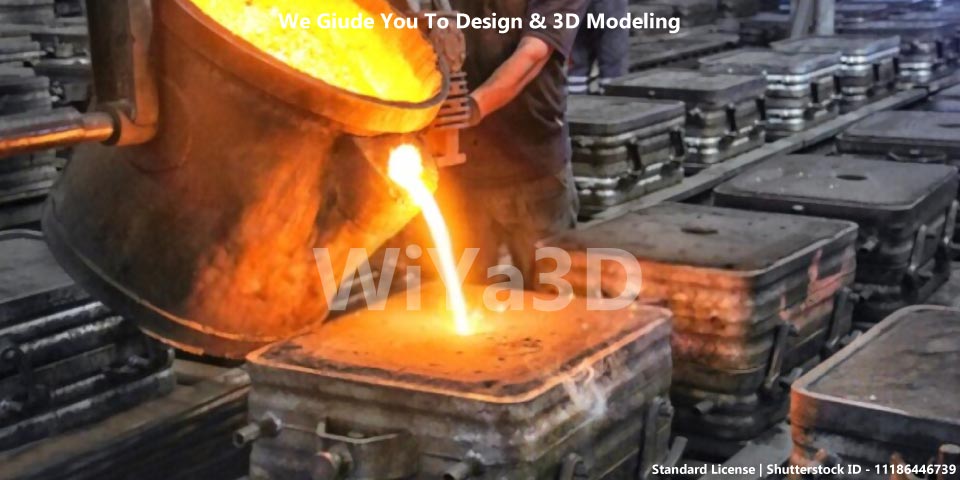
In a machine shop, work materials often arrive in the form of billets, tubes, blocks or bars, sections, beams, and other shapes. Therefore, the first operation in the workshop is often to cut the material into the required size and initial shape. This is typically done through sawing, flame or gas cutting, or water jet cutting operations. These processes are used to create the initial workpiece from a larger piece of material.
Sawing
A sawing machine is a machine tool that is used to cut materials, such as metal, wood, or plastic, into specific shapes and sizes. There are many different types of sawing machines, including manual and automatic machines, and the choice of machine will depend on the material being cut and the desired precision of the cut.
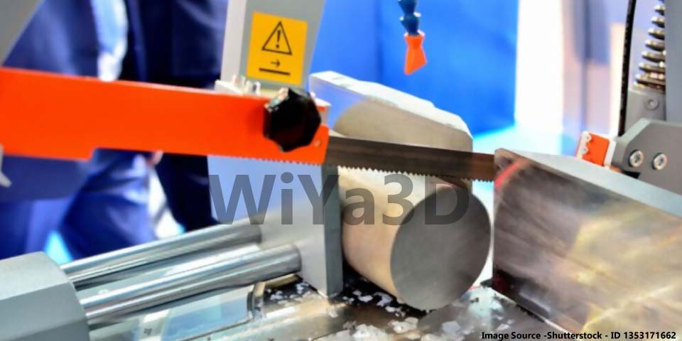
One common type of sawing machine is a bandsaw, which uses a continuous loop of saw blade to make straight or curved cuts. Another type of sawing machine is a circular saw, which uses a circular blade to make straight cuts. There are also specialized sawing machines for cutting specific materials, such as a cold saw for cutting metal or a panel saw for cutting wood.
In a machine shop, sawing machines are often used to cut workpieces to the desired size and shape before they are machined further using other tools and techniques.
Broaching
Broaching also similar to the sawing operation. However broaching tool has two main difference.
- Teeth height increase along the tool, which result in increase of depth of cut as tool progress.
- Teeth width increase along the tool thereby width of cut will increase as tool progress.
Therefore in broaching process material removal rate is higher than the sawing process. This process used in groove cutting & internal keyway cutting in gear/pully.
If the workpiece material come in as casting block to workshop. Then above sawing or broaching processes will not require.
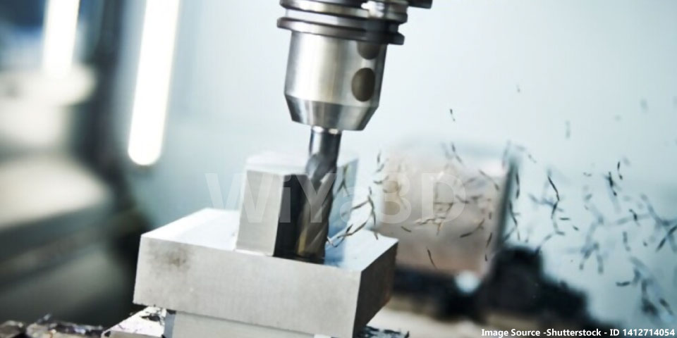
Drilling
Drilling is the process of creating a hole or tunnel in a solid material, such as wood, metal, or rock. There are several methods that can be used to drill a hole
- Manually operated carpenter drill
- Hand drill
- Pedestal Drill
- Lathe machine
- Radial arm drill
Boring
Boring is a machining process that involves the use of a boring tool to enlarge or finish a hole that has already been drilled or cast. The boring tool is a rotating cylindrical cutting tool with a single point or multiple cutting edges. It is mounted on a boring machine or a lathe and is used to remove material from the inside surface of a hole to create a precise diameter and straightness.
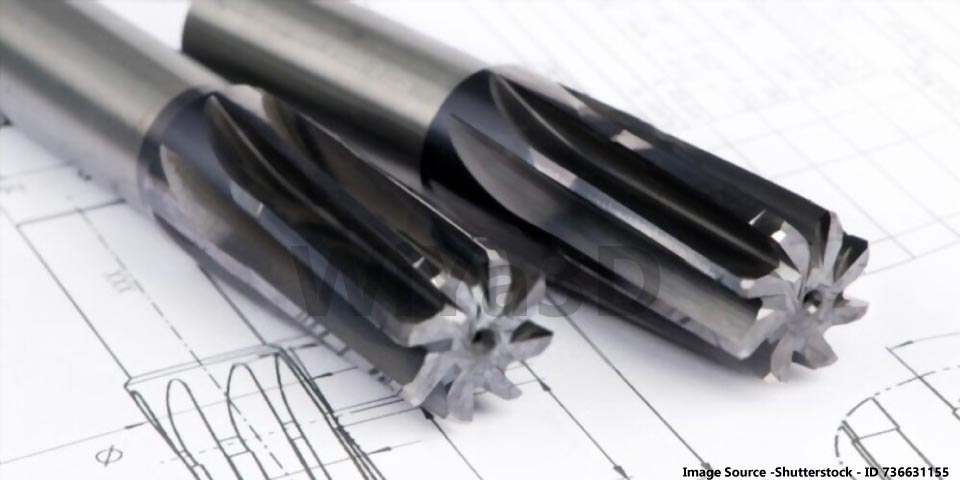
Reaming
Reaming is a machining process that involves the use of a reamer to finish or enlarge a previously drilled or cast hole to achieve a precise diameter and smooth finish. A reamer is a rotating cutting tool with a series of cutting edges along its length, and is typically made of high-speed steel or carbide.
Reaming is typically used to produce holes with precise diameters and finishes, and is often used in the manufacturing of machine parts and automotive components. It is a relatively slow process compared to drilling, but is more accurate and produces a smoother finish.
There are several types of reaming operations, including hand reaming, which uses a manual tool to turn the reamer, and machine reaming, which uses a machine tool, such as a lathe or CNC machine, to turn the reamer.
Thread Tapping
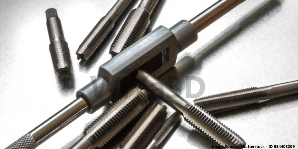
Thread tapping is the process of creating a thread on the inside surface of a hole, typically for the purpose of accepting a screw or bolt. It is a common operation in manufacturing and construction, and is typically performed using a tap, which is a rotary cutting tool with cutting edges along its length.
To tap a thread, the tap is inserted into the hole and rotated, cutting a thread into the material as it is withdrawn. The tap can be held by hand or mounted in a tap handle or a machine tool, such as a drill press or CNC machine.
Shaping
Shaping process used to produce the flat surface & grooves. In shaping operation tool reciprocatively move against workpiece and during forward stroke the material only get removed. While return stroke is free.
Every end of stroke of the shaping tool, the workpiece advanced perpendicular movement of the tool. Therefore material removal is progress in entire workpiece or set limits. Once one layer is completed, workpiece raised relative to tool direction and start shaping next layer.
With the shaping operation, it can machined flat surfaces, rectangle grooves, V/U shape grooves and for keyway machining in gears/pully use shaping machining operation
Planing
Unlike shaping operation, during planer operation, the tool kept stationary while workpiece reciprocate. This operation mainly used to obtain planer surface.
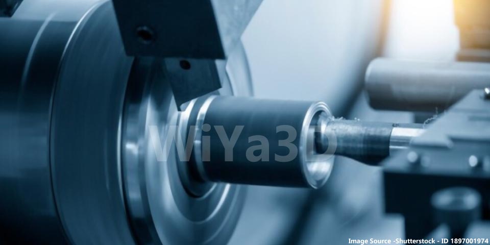
Turning
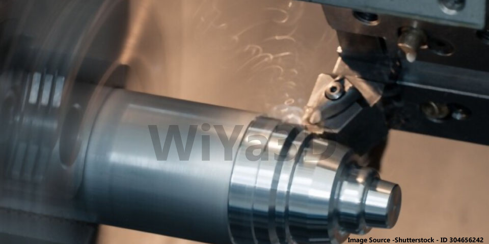
Turning operation used to machine the cylindrical or axi-symmetrical surfaces. And Lathe or CNC turn machine are use for turning operation, where workpiece turn around it’s axis and tool move against material to remove materials in chip form.
Although lathe machine also used for drilling, boring, facing,..etc operations.
Milling
Milling process that rotate circular cutter with cutting edges to remove material by advancing cutter on workpiece. Mainly there are two milling machine types vertical & horizontal. And milling operation follow to get very simple to complex surface/feature with precision machining specially in mold/die making industry.
Grinding
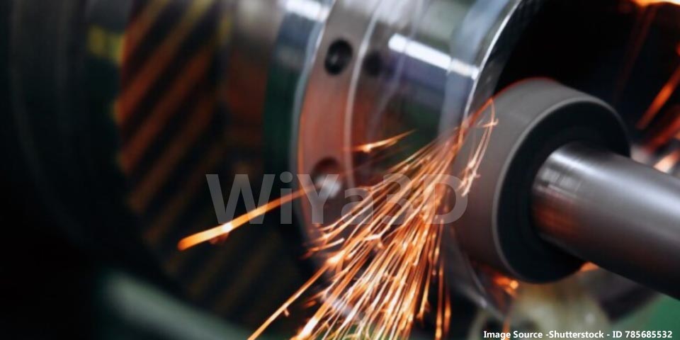
During material removal process the product follows number of tooling operation to obtain final shape. And mostly surface finish during machining process depend on,
- Cutting tool step depth
- Cutting tooling operation step over
- Tool material & workpiece material
- Machine process speed
Therefore, the grinding operation use to obtain much finer surface finish. Very large/countless number of grinding particle, powder grains called grit are embedded in grinding tool. This grinding tool used to machine and obtain surface with finer surfaces, that depend on how fine the grit size.
There are few type of grinding process, which are
Surface Grinding – Grinding operation that carried out on flat surface is called surface grinding. The grinding machine can be select mainly that tool rotate in horizontal or vertical axis depend on machining requirement. While workpiece move in rotary or reciprocating motion that makes 4 combination of grinding machine setup types.
Cylindrical Grinding – In case product/part with cylindrical surface have to grind. Need to follow cylindrical grinding process. That cylindrical grinding tool rotate parallel axis to the workpiece. This relative rotation grind the cylindrical surface of cylindrical workpiece. Relative speed need to adjust for grinding requirement.
Centerless Grinding – Unlike other grinding process, this method use two grinding wheels in between cylindrical workpiece. Also workpiece guided in both end and feed the workpiece in order to grind the whole length require progressively without resetting grinding setup.
Honing
Honing is basically grinding process that used to obtain much finer finish. This can archive by grinding with much finer grit grinding wheels.
Lapping
In order to go beyond finishing of grinding or honing the lapping grinding operation use. The grit sizes with much more finer mixed with oil or some compounds and carried out the grinding. Which produce the more finer finish with much higher surface finish quality. This operation use final finishing of valve in IC engines.